


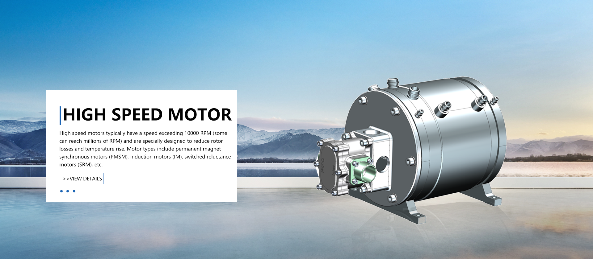
High speed motors typically have a speed exceeding 10000 RPM (some can reach millions of RPM) and are specially designed to reduce rotor losses and temperature rise. Motor types include permanent magnet synchronous motors (PMSM), induction motors (IM), switched reluctance motors (SRM), etc. It has high power density, high efficiency, low vibration noise, and needs to be matched with high-speed bearings (such as magnetic levitation bearings).
Material selection: High strength alloys (such as titanium alloys) or carbon fiber composite materials are used to withstand high-speed centrifugal forces. Permanent magnet synchronous motors (PMSM) commonly use neodymium iron boron (NdFeB) magnetic steel, which is protected by carbon fiber sheaths or metal sleeves.
Topology optimization: Solid or hollow rotor design to reduce inertia, surface mount (SPM) or built-in (IPM) permanent magnet layout, IPM is more suitable for high-speed working conditions (high mechanical strength).
Dynamic balance: It needs to reach G0.4 level (ISO 1940 standard) and use laser dynamic balance correction technology.
Core material: amorphous alloy or ultra-thin silicon steel sheet (0.1~0.2mm) to reduce high-frequency eddy current losses, using segmented core to reduce harmonics.
Winding technology: Litz wire or multi-layer flat wire winding to reduce skin effect losses; Adopting vacuum impregnation technology to enhance heat dissipation and insulation.
Cooling system: oil cooling (direct oil injection cooling) or dual cycle water cooling (internal flow channel design of stator housing), with a power density of up to 5-10 kW/kg.
High speed bearings: ceramic hybrid bearings (Si3N4 spheres) or magnetic levitation bearings (non-contact, with a speed of up to 50000 rpm or more), lubricated with oil air lubrication or micro lubrication (MQL).
Bearing dynamics modeling: It is necessary to consider the stiffness damping characteristics to avoid resonance caused by critical speed.
Multi physics field coupling analysis: Optimizing the cooling channel through CFD simulation, using direct slot cooling for the stator, and aerodynamic design for the rotor (such as wind resistance minimization structure).
Temperature monitoring: Real time monitoring of hot spot temperature using embedded fiber optic sensors or PT100.
The high-speed motor controller is an intelligent drive core designed specifically for high-speed and high dynamic response scenarios. Through advanced control algorithms and high reliability hardware architecture, it achieves millimeter level precision control of motor speed and torque, and is widely used in fields such as electric vehicles, aerospace, precision manufacturing, fuel cell air compressors, high-speed milling spindles, unmanned aerial vehicle propulsion systems, etc., which require strict speed and reliability.
Device selection: SiC MOSFET (withstand voltage above 1200V, switch loss 70% lower than IGBT) or GaN HEMT (suitable for ultra-high frequency applications).
Module packaging: Adopting double-sided heat dissipation (DSC) or three-dimensional packaging (such as SKiN technology) to reduce parasitic inductance (<10nH).
Thermal interface material: nano silver sintered or phase change material (thermal conductivity>5 W/mK).
Capacitor group: Thin film capacitors (low ESR) are connected in parallel with ceramic capacitors to suppress high-frequency ripple; The fluctuation of bus voltage should be controlled within ± 2%.
Stacked busbar: Insulation film (such as polyimide) is sandwiched between copper bars to reduce parasitic parameters (inductance<50nH).
Processor: Multi core DSP (such as TI C2000 series)+FPGA architecture, realizing FOC (Field Oriented Control) and weak magnetic control (speed extension to more than 3 times the base speed).
Sampling circuit: 16 bit ADC (sampling rate>1MSps), Hall+rotary dual feedback redundant design.
High frequency PWM modulation: using space vector modulation (SVPWM) or DPWM (reducing switching losses).
Adaptive control: Online parameter identification based on MRAS (Model Reference Adaptive) to compensate for inductance saturation effects at high speeds.
Filter design: Common mode choke+π - type filter, meeting CISPR 25 Class 5 standard.
Structural shielding: aluminum alloy shell+conductive pad, gap size<λ/20 (λ is the highest interference frequency wavelength).


